
"Tooling" and "fixture" get used interchangeably on shop floors, but they mean different things to engineers. Getting the terminology right matters because it shapes design decisions.
This article breaks down tooling versus fixtures, walks through fixture types, explains the 3-2-1 locating principle, and covers how these choices affect weld quality and compliance on regulated projects.
Key Takeaways
- Tooling is the umbrella term for all production aids; a fixture is one specific type that holds and locates a workpiece
- The 3-2-1 principle uses six contact points to eliminate five degrees of freedom before clamping
- Well-designed fixtures cut rework, improve repeatability, and support inspection-ready, traceable manufacturing
- Welding fixtures must account for thermal distortion in ways static machining fixtures never do
What Is Tooling? Defining the Foundational Concept
Tooling is the broad category covering any device built specifically to aid production without becoming part of the final product. According to Carr Lane's manufacturing-engineering reference, a "tool" is a generic workholder term that encompasses both jigs and fixtures.
Tooling categories include:
- Cutting tools — drills, end mills, lathe tooling
- Forming and press tools — dies, punches, stamping equipment
- Workholding devices — vises, chucks, clamps
- Welding apparatus — positioners, purge chambers, fixtures
- Assembly aids — alignment tools, torque fixtures
- Inspection gauges — go/no-go gauges, coordinate measuring fixtures
All fixtures are tooling, but not all tooling is a fixture. A drill bit is tooling. A vise is tooling. Neither qualifies as a fixture in the strict engineering sense. A fixture’s job is specific: hold, support, and locate a workpiece in a fixed position.

What Is a Fixture? Understanding Its Role
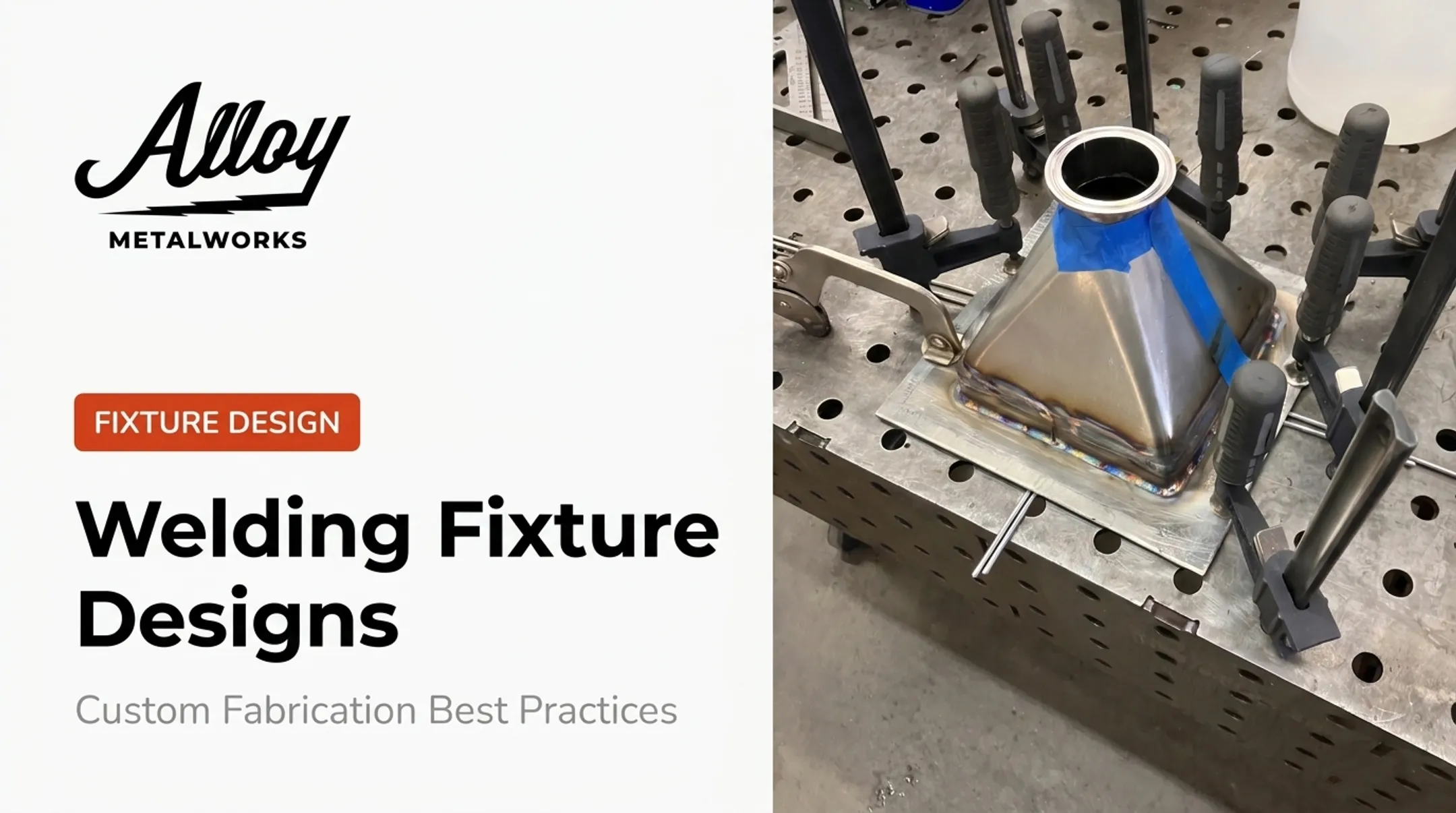
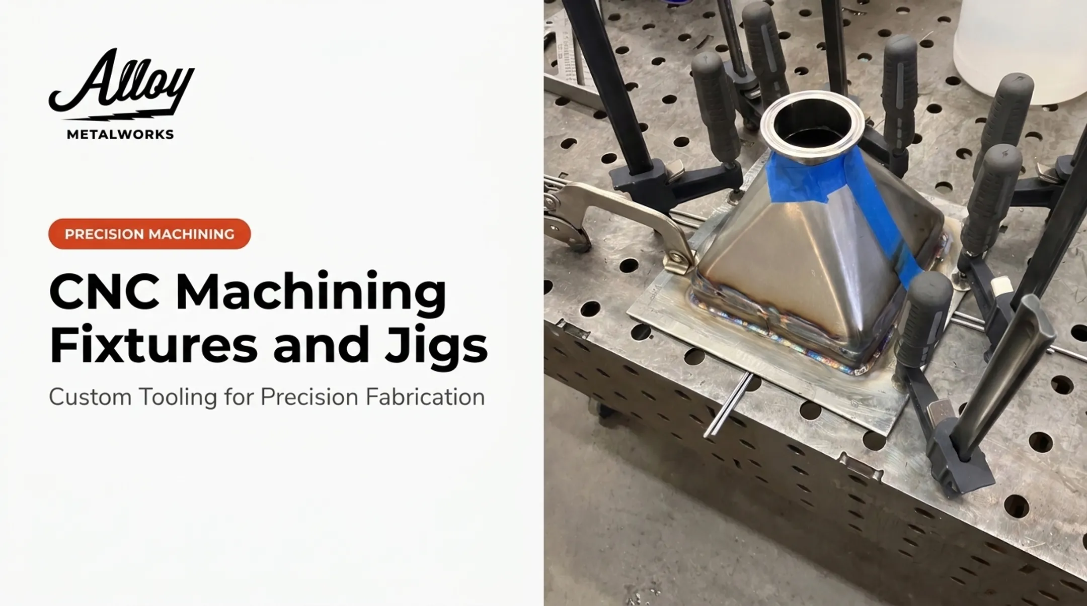
A fixture is a device that holds, supports, and locates a workpiece in a fixed, repeatable position during machining, welding, or inspection. It doesn't guide the cutting tool. It just keeps the part exactly where it needs to be.
Fixtures vs. Jigs: Why the Distinction Matters
People confuse fixtures and jigs constantly, and the difference isn't whether they hold the part—both do.
Carr Lane's definitions draw the line elsewhere: a jig guides the cutting tool, typically using drill bushings, while a fixture references the cutting tool using set blocks or feeler gauges rather than physically directing it. The distinction is about the workholder's relationship to the tool, not the holding function itself.
That tool relationship plays out differently in machining and welding:
- In machining, a jig can physically steer a drill bit through a bushing
- In welding, there's no cutting tool to guide. The welder or robot controls the torch path. The fixture's job is purely to hold geometry steady against heat, gravity, and clamping force
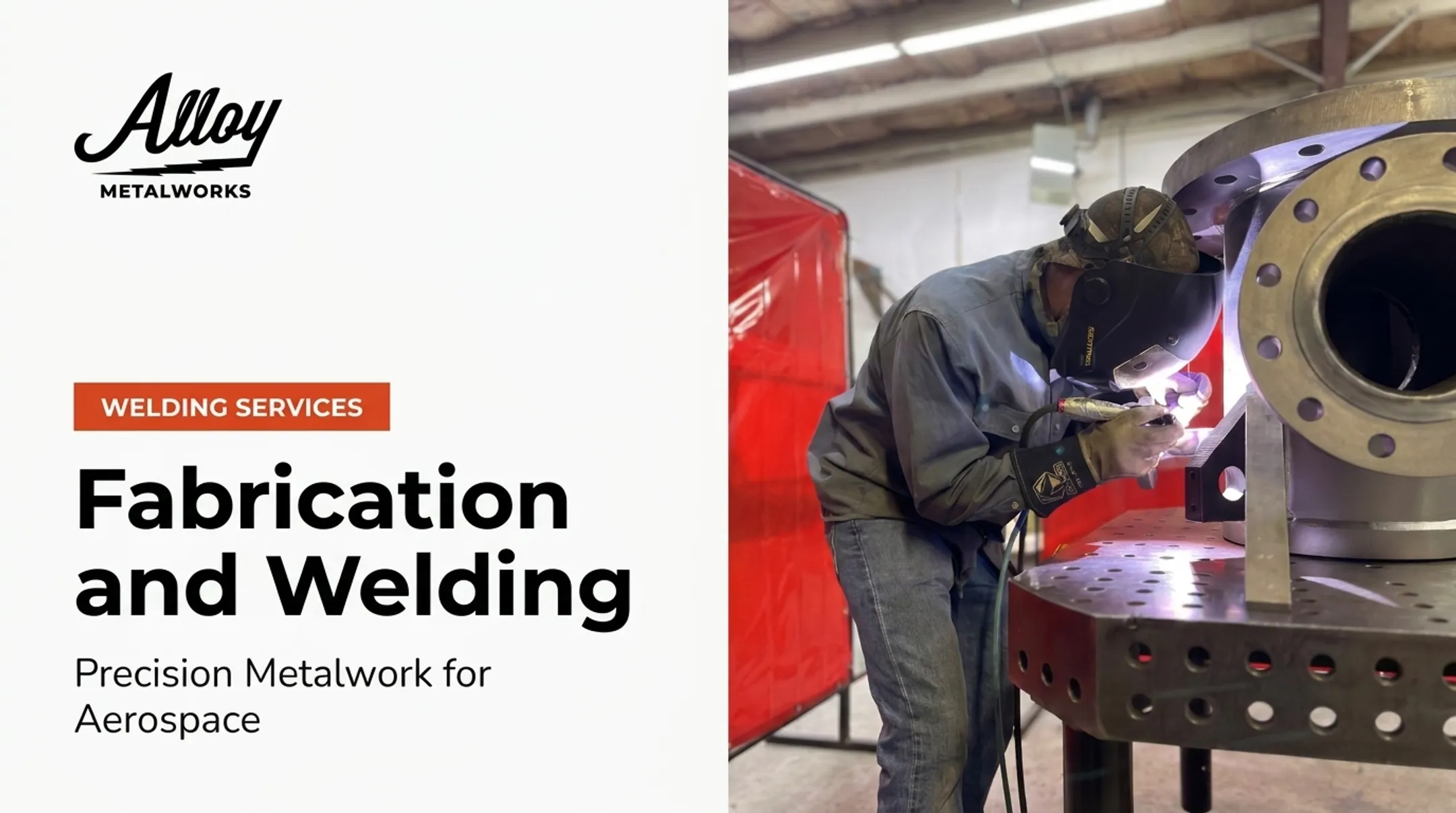
That's why welding applications almost always use the term fixture, not jig. Alloy Metalworks builds custom frames, fixtures, and mechanical assemblies for aerospace work—including thin-wall and lightweight structures—so part geometry stays locked through heat, gravity, and clamping force.
Types of Tooling and Fixtures Used in Manufacturing
Common Tooling Types
Shop floors run on general workholding gear and machine-specific fixtures:
- Frames — structural support for larger assemblies
- Jacks — height and angle adjustment during setup
- Vises and clamps — general-purpose workholding
- Machine-specific fixtures — turning, milling, indexing, and grinding setups shaped around each machine tool's motion
The Three Main Categories of Fixtures
Fixtures fall into three broad classifications. The American Society of Tool and Manufacturing Engineers' Handbook of Fixture Design frames workholding around machining, assembly, and inspection.
Carr Lane also treats welding and inspection fixtures as distinct families:
| Category | Production Stage | Primary Function |
|---|---|---|
| Machining fixtures | Cutting/forming | Resist cutting forces, maintain tolerance |
| Assembly/welding fixtures | Joining | Hold parts in position through heat and clamping cycles |
| Inspection fixtures | Quality verification | Orient the part to expose features, using light, quick-acting clamps |
Each serves a different point in the production lifecycle, and each has different constraints. A machining fixture needs to survive cutting forces. A welding fixture needs to survive heat. An inspection fixture needs to get out of the way fast so features stay visible.

The 3-2-1 Principle in Fixture Design
The 3-2-1 principle is the foundational method for eliminating a workpiece's degrees of freedom before clamping. It works by placing six locating points across three mutually perpendicular planes:
- Three points on the primary plane (the largest, most stable reference surface)
- Two points on the secondary plane (perpendicular to the primary)
- One point on the tertiary plane (perpendicular to both) Carr Lane's engineering reference describes locators this way: they take the principal machining forces, while clamps hold the workpiece against those locators without changing its shape. That's a critical distinction. Locators define position. Clamps just hold the part there.

Applying 3-2-1 to Irregular Parts
Cast or forged parts rarely have perfectly flat mounting surfaces. For these, the same Carr Lane reference recommends adjustable, variable-height supports and equalizing supports. They float slightly to accommodate surface variation instead of forcing rigid three-point contact onto an uneven casting. Published research backs the method. A 2001 ASME Journal of Manufacturing Science and Engineering study on deterministic 3-2-1 schemes for machining fixtures modeled admissible locator regions against disturbing forces from cutting operations. Locator placement isn't guesswork. It's calculable.
Why Over- or Under-Constraining Fails
Get the locator count wrong and you get problems fast:
- Under-constraining leaves degrees of freedom uncontrolled, so the part shifts during machining or welding
- Over-constraining forces a rigid part against locators that don't align, inducing stress, distortion, or unsafe clamping loads Neither produces a repeatable, inspection-ready result.
Adapting 3-2-1 for Welding Heat
Machining fixtures deal with static cutting forces. Welding fixtures deal with thermal expansion, which moves the part mid-process. That is why welding fixtures often swap rigid locators for spring-loaded pins. These retract under pressure and extend to maintain contact as the part expands and contracts. Carr Lane notes these devices provide consistent positioning force through the movement cycle, rather than fighting it.
Fixture Design Challenges for Precision Welding and Exotic Alloys
Static machining fixtures deal with predictable cutting loads. Welding fixtures fight something less predictable: heat that moves through the part unevenly and pulls metal out of shape as it cools.
A 2007 study in the Journal of Achievements of Materials and Manufacturing Engineering tested welded U-shaped steel sections cooled inside a fixture versus cooled freely. The fixture reduced distortion, and the study also found that higher heat input increased distortion while faster weld speed reduced it — reinforcing why clamping sequence and heat management have to be designed together, not treated as separate problems.
Managing Heat at the Fixture Level
Common thermal-control strategies include:
- Chill blocks — copper or aluminum inserts that absorb welding heat and help control interpass temperature
- Strategic clamping sequences — releasing and reapplying clamps in a planned order as the weld cools
- Spring-loaded locators — compensating for expansion instead of resisting it rigidly

In day-to-day work at Alloy Metalworks, Inconel 617 makes that tradeoff concrete: too much heat risks distortion and metallurgical compromise; too little sacrifices fusion. Fixture design carries as much of that balance as welder technique.
Exotic Alloys Add Contamination Risk
Titanium, Inconel, and Hastelloy don't just distort under heat. They also oxidize if exposed to atmosphere during welding. Huntingdon Fusion Techniques describes flexible purge enclosures for titanium that monitor oxygen down to 10 ppm, using a gas entry port, exhaust valve, and purge monitor. For nickel alloys like Inconel 740H, target internal purge levels run around 50 ppm or lower, or 20 ppm for stringent work.
Fixture materials matter here too. For nickel-iron alloys like 800HT, carbon-steel vises and work surfaces can embed iron particles into the alloy, creating rust-initiation sites before the part ever sees service. Non-ferrous or protected tooling avoids that failure mode entirely.
This is where fixture design and code compliance intersect. AWS D17.1 Class A governs flight-critical fusion welding, and even minor visual imperfections can trigger immediate rejection. ASME Section IX governs welding procedure qualification. Neither standard prescribes a specific fixture layout, but both depend on the fixture producing a consistent, repeatable, inspectable result.
Alloy Metalworks builds custom purge chambers and fixtures into its precision welding process for flight-critical and high-performance alloy work, so contamination control happens at the fixture stage—before inspection failures, delays, or rework show up downstream.
Choosing the Right Fixturing Solution for Your Production Environment
Fixture selection comes down to production volume and part complexity:
- High-volume runs favor dedicated, custom-built fixtures optimized for one part geometry
- Low-volume or prototype work favors modular, reconfigurable fixturing that adapts across multiple jobs
- Hybrid fixturing blends modular flexibility with permanent stations for shops running mixed production
When evaluating a fixturing approach, weigh:
- Part complexity: irregular geometry needs adjustable or equalizing supports
- Floor space: dedicated fixtures take up permanent real estate
- Inspection needs: design inspection fixtures alongside production fixtures, not as an afterthought
Alloy Metalworks designs fixtures for accuracy across production volumes inside its ISO 9001-controlled environment, and pairs them with orbital and automated welding to cut setup variability on repeat runs.
Frequently Asked Questions
What does "tooling" mean?
Tooling is the umbrella term for any device built to aid production without becoming part of the final part. It includes cutting tools, workholders, fixtures, jigs, and inspection gauges.
What is a fixture?
A fixture is a workholding device that locates and secures a part in a fixed, repeatable position during machining, welding, or inspection. It doesn't guide the cutting tool itself.
What are the types of tooling?
Common tooling types include frames, jigs, machining fixtures (turning, milling, indexing, grinding), vises and clamps, and holding fixtures for welding or assembly.
What are the three types of fixtures?
Fixtures generally fall into machining fixtures, assembly/welding fixtures, and inspection fixtures. Each supports a different stage of production, from cutting to joining to quality verification.
What does fixture design mean?
Fixture design is the engineering process of determining clamping, locating, and support features needed to hold a workpiece accurately. It accounts for cutting forces, thermal expansion, and part geometry.
What is the 3-2-1 principle in fixture design?
The 3-2-1 principle uses six contact points across three perpendicular planes (three, then two, then one) to constrain a workpiece's degrees of freedom before clamping force is applied.