
A robot can't search for a joint the way a human welder does, adjusting on the fly for a part that's sitting a few thousandths off. If the fixture places the part wrong, the robot welds the wrong spot with total confidence. This guide covers fixture design principles, the main fixture types, common mistakes, and what changes when you're welding titanium, Inconel, or anything that needs to satisfy AWS or ASME auditors.
Robotic and cobot welding is spreading fast across aerospace, energy, and advanced manufacturing, and that growth is putting real pressure on fixture design. As the American Welding Society has noted, robotic welding is becoming standard in industrial manufacturing, with skilled labor shifting toward programming, quality assurance, and system oversight — work that depends entirely on fixtures holding their end of the bargain.
Key Takeaways
- Fixtures determine whether a weld joint stays within tolerance cycle after cycle
- Position tolerance at the joint should repeat within half the welding wire diameter
- Datum strategy, controlled clamping force, and torch access anchor every fixture design
- Exotic alloys and code-compliant welding need extra fixture considerations, including purge setups and documentation
- Pick modular, dedicated, or outsourced fixture design based on production volume and part complexity
What Is a Robotic Welding Fixture and Why It Matters
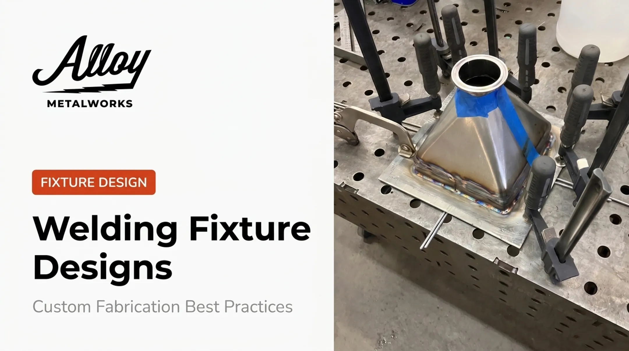
A robotic welding fixture is tooling that locates, supports, and clamps a workpiece so the robot can follow a fixed, repeatable path. That's it. But that simple job description carries enormous weight, because robots can't self-correct.
A human welder sees seam variation and adjusts the torch angle or travel speed without thinking about it. A robot follows the taught path regardless of what's actually in front of it. If the part shifted 0.03 inches during loading, the robot welds 0.03 inches off-seam — and doesn't know it happened.
Primary Functions of a Robotic Weld Fixture
Every robotic fixture has three jobs:
- Provide torch access at correct approach angles for the full weld path
- Locate the joint within the process window — commonly ± half the wire diameter for GMAW
- Clamp with repeatable, gap-free positioning so the part can't move mid-cycle
Get any of these wrong and the costs stack up fast: rework, longer cycle times, inconsistent penetration, and rejected parts. Underfilled joints from poor fit-up can require more weld metal than a properly fixtured joint. That hidden cost shows up in cycle time and consumables long before anyone flags it as a quality issue.

Key Design Principles for Robotic Welding Fixtures
Good fixture design isn't guesswork. It follows a handful of principles that, when skipped, are almost always the root cause when a robotic cell starts producing inconsistent welds.
- Datum strategy first: Use primary datums to locate the part, secondary datums to orient it, and tertiary datums to prevent rotation. Skip this hierarchy and parts only "mostly" locate the same way, which isn't good enough for a process with zero self-correction.
- Clamping philosophy over clamp count: Locate the part first, then apply only enough force to hold it, not crush it. Sequence clamps so parts settle naturally instead of torquing into a stressed state that springs back after the weld cools.
- TCP and torch clearance before geometry: Run a CAD collision check on the full tool center point path, not just the nominal weld location. Skip this and cable routing or torch body collisions surface during commissioning.
- Respect thermal behavior: Over-rigid clamping increases distortion, especially in aluminum and thin-gauge assemblies. Sometimes less clamping force is the right move, not more.
- Tack welding in the fixture system: On multi-pass welds, tacks preserve geometry between fixture release and the final pass locking the part in.
- Validate before production: Run a documented repeatability test across different parts and operators. If joint position doesn't repeat under those conditions, it won't repeat on the floor either.
Types of Robotic Welding Fixtures
Modular Fixturing Systems
Standardized, reconfigurable components suit low-to-medium volume runs, prototypes, and high-mix production. You trade some rigidity for the ability to reconfigure quickly between part families — which matters a lot for shops running prototypes and small-batch work alongside production jobs.
Dedicated/Custom Fixtures
Purpose-built fixtures deliver maximum rigidity and accuracy for high-volume, single-part production. They cost more upfront and don't flex to new part geometries, but for a stable product family, that rigidity is what keeps every part in tolerance.
Both modular and dedicated setups can use pneumatic and hydraulic clamping. These systems standardize clamp force across operators and shifts, speed up cycle time, and support proximity sensing so the robot doesn't start welding until the clamp confirms it's closed.
| Fixture Type | Best For | Tradeoff |
|---|---|---|
| Modular | High-mix, prototyping, small batches | Less rigid, faster changeover |
| Dedicated | High-volume, stable part family | High rigidity, higher upfront cost |
| Pneumatic/hydraulic clamping | Either type | Standardizes force, adds controls/maintenance |

That tradeoff shows up clearly in the shop. Alloy Metalworks' prototyping and small-batch work regularly involves custom tools and fixtures built alongside the parts themselves — a one-off fixture designed around a specific part's tolerances beats a generic setup every time.
Special Considerations for Exotic Alloys and Regulated Industries
Titanium and nickel-based alloys like Inconel and Hastelloy don't forgive fixturing shortcuts. Titanium needs inert gas purge chambers, and shielding coverage has to hold through the entire weld, including the trailing area and backside, where contamination most often sneaks in. Backing gas should stay in place for at least the first several passes on titanium work.
Sanitary stainless systems, governed by AWS D18.1 and USDA 3-A standards, need fixtures that avoid contamination and support crevice-free, cleanable joint geometry. A fixture that leaves spatter traps or inaccessible surfaces defeats the purpose of hygienic design.
Flight-critical and ASME Section IX code welding raise the bar further. Fixture-driven repeatability has to be documented through weld procedure specifications and traceability records. Under AWS D17.1 Class A, which governs flight-critical components, visual contamination alone can disqualify a weld — even if it passes destructive and radiographic testing.
This is where Alloy Metalworks' fabrication approach fits:
- Welds all grades of titanium using custom inert chambers and purge setups built to prevent oxidation
- Holds documented nickel-alloy capability across Inconel 600, 601, 617, 625, 718, Hastelloy, and Incoloy 800HT
- Operates under ISO 9001-controlled processes with AWS and ASME certifications
For companies whose fixturing needs intersect with code compliance and exotic alloys, that mix of engineering awareness and documentation discipline is the difference between a weld that looks fine and one that's inspection-ready.

Common Fixturing Mistakes That Hurt Weld Quality
These design and process errors show up often in robotic welding cells and cut into weld quality:
- Designing to nominal CAD dimensions instead of real part tolerances and variation; parts never come in exactly as drawn
- Over-constraining with excessive clamp force, which stresses the part and shows up as distortion after the weld cools
- Ignoring torch and cable clearance during design, which leads to collisions or restricted access found only at commissioning
- Skipping wear and maintenance planning, and assuming a fixture holds accuracy indefinitely instead of building in replaceable locating components
That last one catches a lot of shops off guard. A documented case from a Cal Poly robotic welding project found parts failing spec because the fixture itself warped during assembly, not because the robot drifted. Qualify the fixture for stiffness and stability before you qualify production welds on it.

Choosing the Right Fixture Partner or Approach
Build in-house when parts are simple and you already have engineering capacity to spare. Outsource when part complexity, tight tolerances, or code compliance push past what your internal team handles regularly.
Before starting any fixture project, specify:
- Material type — aluminum, titanium, and nickel alloys each behave differently under clamping and heat
- Part geometry and tolerances — including realistic variation, not just nominal CAD
- Required torch access — clear path along the full weld sequence
- Target cycle time and production volume — drives automation level and fixture durability
- Safety and compliance requirements, including any applicable AWS or ASME codes
Strong fixture partners also support weld procedure development and process validation, not fixture hardware alone.
Alloy Metalworks' engineering support covers weld-joint design and material-specific contamination-risk mitigation. For complex or regulated parts, that work pairs with fixture design because the fixture and the weld procedure have to be validated together.
Frequently Asked Questions
Are there automated welding machines?
Yes. Robotic and cobot welding machines are widely used in manufacturing. They rely entirely on fixtures to maintain positional accuracy, since the robot itself can't detect or correct for a misplaced part.
What is the ideal tolerance for a robotic weld joint?
A common guideline for GMAW is joint position repeatability within half the wire diameter (for example, ±0.022 inches for 0.045-inch wire). GTAW tolerances are tighter and should be set by the drawing and qualified procedure, not borrowed from GMAW rules.
What's the difference between a cobot welding fixture and a traditional robotic welding fixture?
Cobots typically work in lower-volume, higher-mix settings, so fixtures often prioritize flexibility and fast changeover over maximum rigidity. The core requirements (repeatable location, secure clamping, and torch clearance) still apply.
Can existing manual welding fixtures be reused for robotic welding?
Usually not. Manual fixtures are built around a human operator's ability to compensate for small variations, and they typically lack the rigidity and repeatability a robotic system needs to hold tolerance cycle after cycle.
How often should welding fixtures be inspected or maintained?
Locating and clamping points wear over time, especially with spatter buildup near contact surfaces. Set a risk-based inspection schedule and always re-check dimensions after any collision, repair, or noticeable quality drift.
Do robotic welding fixtures need to differ for exotic alloys like titanium or Inconel?
Yes. Titanium fixtures need purge chambers and sealed gas coverage to prevent oxidation, while code-compliant work on nickel alloys requires documentation and traceability built into the fixturing process from the start.