
Key Takeaways
- Fillet welds join angled surfaces (usually 90°) with a triangular cross-section; butt welds join surfaces in the same plane.
- Strength is governed by throat size relative to base metal thickness, not visible leg length.
- Typical uses span structural steel, aerospace hardware, pressure vessels, and sanitary piping.
- AWS D1.1 and ASME Section IX set minimum sizes and qualification rules for code work.
- Overwelding wastes filler and adds distortion; underwelding risks joint failure under load.
What Is a Fillet Weld?
A fillet weld is a weld of approximately triangular cross-section that joins two surfaces at roughly a right angle, typically in a lap, T-, or corner joint. That's the AWS-based definition. Geometry drives everything else about how the weld performs.
Anatomy of a Fillet Weld
Every fillet weld has a few key features:
- Leg – the size dimension measured along each base metal surface
- Toe – where the weld metal meets the base metal
- Face – the visible outer surface of the weld
- Root – the point where the two surfaces intersect, deepest into the joint
- Throat – measured from the root to the face; this is what actually determines strength
The throat, not the leg, is the number engineers use to calculate load capacity. For an equal-leg fillet, the theoretical throat runs about 0.707 times the leg size, a well-documented geometric relationship rather than a strength rating in itself.

Naming confusion: People often call fillet welds "T-welds," "corner welds," or "lap welds." Technically, those describe the joint configuration, not a separate weld type. A more accurate phrase is "a fillet weld in a T-joint," but the informal names are common enough that you'll hear them used interchangeably in shops.
Fillet vs. butt welds: A butt weld joins two surfaces in the same plane and usually requires edge prep, like a bevel or chamfer, to achieve penetration. A fillet weld sits at an angle and typically skips edge prep entirely, which is one reason it's faster and cheaper to produce.
How Fillet Welding Works: Process and Techniques
Making a good fillet weld isn't just running a bead along a corner. It's a sequence:
- Clean the surfaces – remove mill scale, oil, rust, or coatings that cause porosity
- Fit up and clamp – tight, consistent gaps drive penetration and uniform leg size
- Tack weld – hold the joint in position before the full pass
- Weld progressively – single or multiple passes depending on size
- Cool and inspect – controlled cooling avoids cracking, especially on thicker sections
Multi-Pass Welding and Distortion Control
Thicker joints usually need multiple passes instead of one heavy deposit. A single oversized pass concentrates heat and shrinkage in one spot and warps parts. Spreading the weld across passes—and alternating sides when the joint allows—balances those shrinkage forces.
Other distortion-control tactics:
- Use the fewest passes practical, since shrinkage is cumulative
- Sequence welds so forces counteract one another
- Clamp with fixtures or strongbacks to hold alignment during cooling
Once the passes are in, documentation closes the loop. Code-compliant fillet welds need visual inspection at minimum, and often non-destructive testing (NDT) on critical joints, plus traceable records that tie the weld back to a qualified procedure. Those records are how a customer proves the weld will hold under the load and conditions it was designed for.

Specialty Alloys Need Controlled Atmospheres
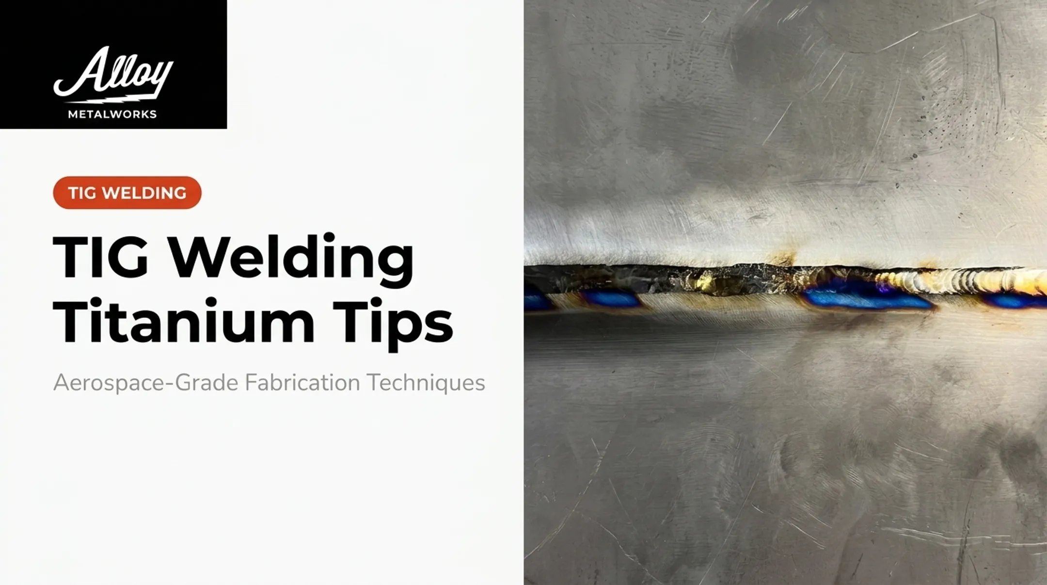
Titanium, Inconel, and other reactive alloys behave differently than mild steel. Titanium in particular oxidizes at elevated temperatures, and exposure to atmospheric oxygen or nitrogen during welding causes embrittlement. That's why titanium work typically requires 100% argon shielding and back-purge setups to keep the weld pool isolated from air.
At Alloy Metalworks, this shows up directly in inspection outcomes. One titanium weld coupon was rejected under AWS D17.1 Class A specifically for purple and blue discoloration—a visible sign the purge wasn't adequate.

In titanium welding, color isn't cosmetic. It's a direct indicator of contamination.
How Strong Are Fillet Welds? Sizing and Strength Rules
Fillet weld strength is governed by throat size, not leg size. A bigger-looking weld isn't automatically stronger if the throat geometry doesn't support it. Fillet welds are strong and reliable, but they carry a lower rated strength than a full-penetration butt weld on the same joint.
Sizing Rule of Thumb
A commonly used starting point: fillet leg size should be roughly ¾ of the thinner base metal's thickness to approach full joint strength. For example, joining two plates where the thinner one is 1/2 inch thick suggests a leg size in the range of 3/8 inch, subject to verification against the actual load case.
Treat that figure as a starting heuristic only. For load-bearing or code-governed work, size the weld from engineering calculation, factoring in:
- Calculated load demand
- Effective throat and effective length
- Base metal thickness limits
- Fatigue and cyclic loading conditions
- The governing construction code's minimum size table
Why Oversizing Costs More Than It Looks Like
Weld volume doesn't scale linearly with leg size. It scales roughly with the square of the leg size. Doubling the leg size on an equal-leg fillet produces roughly four times the cross-sectional weld metal for the same length. That means:
- More filler material consumed
- More heat input into the part
- Higher distortion risk
- Longer cycle time per joint
Lincoln Electric's guidance on this point is blunt: don't overweld, correct sizing saves both weld metal and time. On a production run of hundreds of joints, that difference adds up fast.
Minimum Sizes Aren't About Strength Alone
Codes like AWS D1.1 set minimum fillet sizes based on base metal thickness, separate from what a load calculation might require. These minimums exist mainly to prevent hydrogen cracking and ensure adequate heat input into the joint, not because the load path demands that particular size. A thin, lightly loaded joint can still require a code minimum leg size larger than the load calculation would suggest.

Fillet Weld Symbols and Specifications
Designers communicate fillet weld requirements on drawings using AWS A2.4 weld symbols, not written instructions. Reading these correctly avoids costly misinterpretation on the shop floor.
Key elements of the symbol:
- Reference line – the horizontal line the whole symbol builds from
- Arrow – points to the actual joint location
- Tail – attached at the end of the reference line, carries a WPS reference or process note
- Fillet triangle – a right triangle indicating a fillet weld, with leg size noted to its left
Information placed below the reference line applies to the arrow side of the joint; information above applies to the other side. A symbol on both sides of the line means weld both sides.

For intermittent welds, the drawing shows a segment length followed by a pitch (spacing between segment starts).
- Symbols placed directly across from each other indicate chain intermittent welding
- Offset symbols indicate staggered intermittent welding
If no length is specified, weld the full length of the joint continuously.
Where Fillet Welds Are Used and When to Choose Them
Fillet welds show up across nearly every fabrication discipline:
- Structural steel – buildings, bridges, gussets, and connections
- Aerospace – ground support equipment, airframe brackets, flight-critical structures
- Pressure vessels and machinery – supports, brackets, and non-pressure-boundary attachments
- Sanitary and process piping – tank supports, fittings, and structural attachments in food, pharma, and chemical systems Fillet vs. butt weld: fillets are faster to produce and skip edge prep, but they are generally not intended to achieve complete joint penetration the way a full-penetration butt weld is. For most structural attachments, that trade-off is fine. For flight-critical hardware or high-pressure boundaries, it usually isn't, and the design will call for a groove weld instead. For regulated industries, certification isn't optional. Flight-critical aerospace hardware falls under AWS D17.1 Class A. Pressure-retaining and process work often requires ASME Section IX qualification. Sanitary systems need AWS D18.1 compliance and, often, USDA 3-A standards. Alloy Metalworks, based in Colorado, performs fillet and structural welding under AWS D1.1, D1.2, D1.6, D17.1, and ASME Section IX. The team supports aerospace, energy, and advanced manufacturing clients who need inspection-ready, fully documented welds. That work includes specialty alloys like Inconel, Hastelloy, and titanium, where a purge setup or engineering-calculated procedure often decides whether a weld passes inspection or ends as a rejected coupon.
Frequently Asked Questions
How strong are fillet welds?
Strength depends on throat size and correct sizing relative to base metal thickness, not visual leg size. They are generally rated lower than a full-penetration butt weld covering the same joint.
What is a fillet weld in welding?
It's a weld with a roughly triangular cross-section joining two surfaces at approximately a right angle, most commonly in T-, lap, or corner joint configurations.
What is another name for a fillet weld?
It's often informally called a T-weld, corner weld, or lap weld based on the joint it's used in. Technically, those terms describe the joint type, not a separate weld classification.
What's the difference between a fillet weld and a butt weld?
A fillet weld joins surfaces at an angle and typically skips edge prep; a butt weld joins surfaces in the same plane and usually requires beveling for penetration. Butt welds generally achieve higher rated strength.
How do you determine the correct fillet weld size?
A common starting point is roughly ¾ of the thinner base metal's thickness, but code minimums and engineering calculations based on actual load should always govern the final size.
Do fillet welds require special certification for aerospace or energy applications?
Yes. Codes like AWS D17.1 govern aerospace fusion welding qualification, while ASME Section IX governs procedure and personnel qualification for pressure-related and industrial energy work.