
Poor workholding remains one of the most common causes of rejected parts in precision manufacturing. A part that looks perfect on the print can still fail inspection if the fixture let it shift, tip, or deform during the cut.
This guide breaks down fixture and jig fundamentals, the main types used in CNC environments, design considerations for regulated industries, and when custom fabrication actually makes sense.
Key Takeaways
- Fixtures hold and position a workpiece; jigs guide the cutting tool itself
- Match the fixture to the operation: milling, turning, drilling, or grinding
- Custom-engineered fixtures reduce setup time and downstream inspection failures
- Aerospace and energy clients typically require documented, repeatable fixturing processes
What Is a Fixture in Machining and What Is Its Purpose?
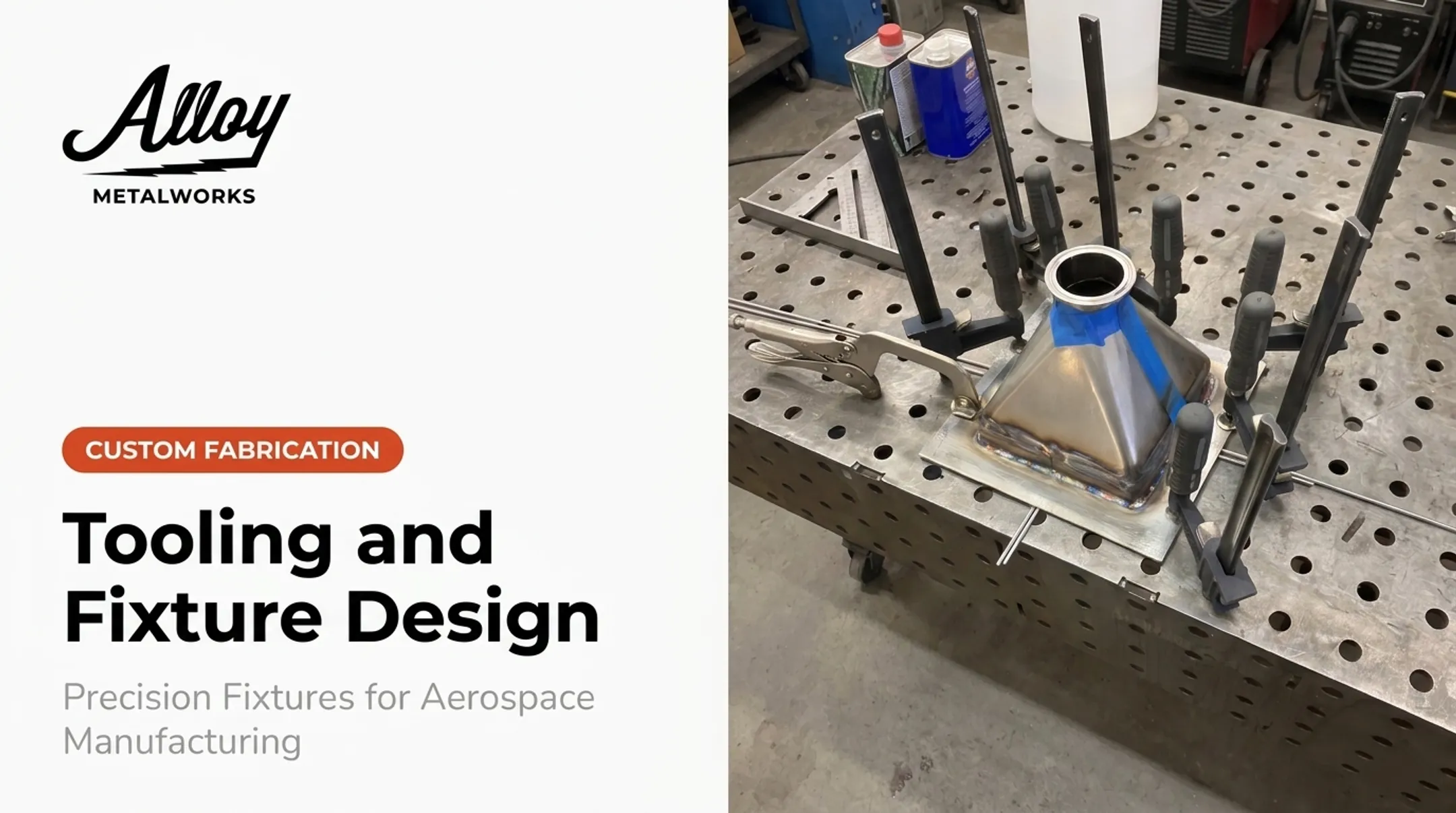
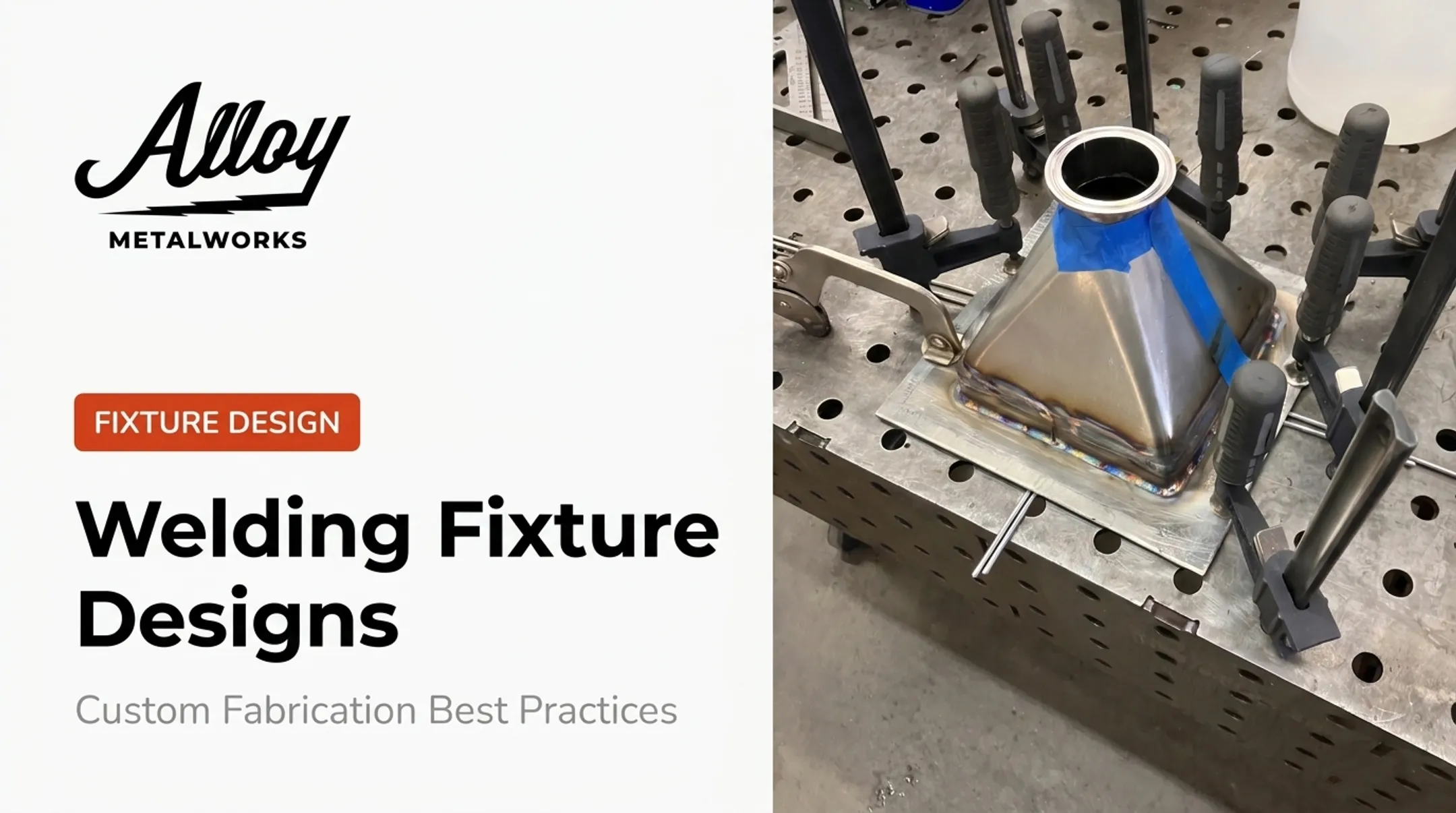
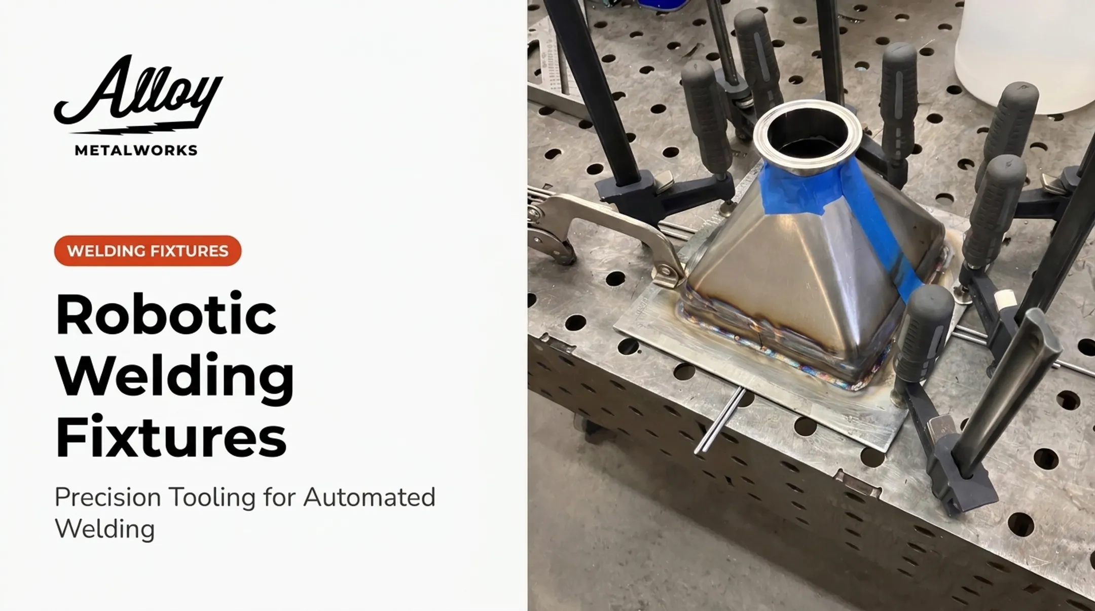
A fixture is a work-holding device that positions and secures a workpiece without guiding the cutting tool. It's purely structural: locate the part, clamp it down, keep it still while the machine does its job.
Fixtures exist to solve four problems:
- Accuracy — consistent part positioning relative to the cutting path
- Repeatability — every part in a batch sits the same way, every time
- Reduced setup time — operators aren't hand-aligning each workpiece
- Operator safety — a secured part can't shift or become a projectile under cutting force
Fixtures vs. Jigs
This confusion comes up constantly. According to Protolabs' comparison of jigs and fixtures, a jig holds the position of the tool during the operation, while a fixture holds the workpiece in a secure position or orientation. The tool guides itself in a fixture setup; a jig physically directs it.
Fixtures also establish the reference and datum surfaces that later operations rely on. If your fixture's datum is off by a few thousandths, every downstream machining step and every inspection measurement inherits that error. Fixture design deserves the same engineering attention as the part itself.

What Are Jigs and Fixtures Used Together For?
Jigs and fixtures often work in tandem, particularly in operations that need both tool guidance and rock-solid part stability. Think drilling, tapping, and reaming where hole placement accuracy depends on both the part staying put and the tool tracking a precise path.
Jigs are especially common in shops without full multi-axis CNC capability. Rather than investing in an expensive 5-axis machine to hit angled hole patterns, a well-designed jig lets a standard drill press produce the same repeatable results.
When jigs and fixtures share a setup, datum selection becomes critical. Cutting Tool Engineering's workholding analysis points out that clamping on the wrong reference face — say, an internal diameter — can let the part tip under drill pressure, making true position nearly impossible to hold. Datum choice isn't a minor detail. It's often the difference between a passing part and scrap.
Well-designed fixtures also build in error-proofing that keeps tandem setups reliable:
- Consistent grip across every load
- Hard datums instead of adjustable stops
- Setups that are physically difficult to load incorrectly
These features cut the odds of a bad part reaching inspection.
What Is a CNC Fixture and How Does It Differ From Manual Fixturing?
A CNC fixture is an engineered work-holding system built specifically for computer-controlled, multi-axis machining. Unlike a manual setup where an operator might adjust and re-check alignment between cuts, a CNC fixture has to hold its position through an entire automated program, sometimes across dozens of tool changes.
That means the fixture design has to account for:
- Cutting forces from multiple directions as the tool approaches at different angles
- Repeatable clamping that performs identically across every part in a production run
- Rigidity sufficient to prevent chatter or deflection during aggressive material removal
Locators in a well-designed fixture resist the primary machining forces, while clamps hold the part against those locators and resist secondary forces. Direction of cutting force can shift throughout a multi-axis program, so this isn't a one-time calculation.
Those shifting loads are also why many shops move to modular and quick-change plates. Systems like ball-lock kits keep one plate mounted on the machine while the operator loads the next part on a second plate offline, cutting idle spindle time.

Common fixture materials include:
- Steel — maximum durability and rigidity for production runs
- Aluminum — strong, lighter plates when mass and handling matter
- 3D-printed polymer — fast first articles for low-volume prototypes, where speed beats long-term wear life
Main Types of Fixtures Used in CNC Machining
Fixtures are grouped by geometry and function, by the machine process they support, and by how they clamp. Matching the fixture type to the part and production volume is what keeps setups repeatable and cycle times under control.
Classification by Geometry and Function
- Plate fixtures: flat base plate with locators and clamps; the most basic and versatile design
- Angle-plate fixtures: used when the locating surface sits at an angle to the machine table
- Vise-jaw fixtures: most common for milling and drilling; fast to set up and suited to simpler geometries
- Indexing fixtures: allow precise rotational repositioning for gear cutting or circumferential hole patterns
- Multi-station fixtures: hold several parts at once to maximize spindle utilization per cycle
Turning Fixtures
Lathe work uses a different set of holding methods since the workpiece itself rotates:
- Chucks: the most common turning workholding; clamp the part by outer or inner diameter
- Collets: tighter concentricity for smaller-diameter round stock
- Faceplates: for irregular shapes that will not fit a standard chuck
- Mandrels: hold parts by an internal bore for outside-diameter machining
Power Source Classification
Fixtures are also categorized by how they clamp:
- Hydraulic: high clamping force and fast, repeatable actuation for high-volume cells
- Pneumatic: quick cycle times and consistent clamp pressure across shift changes
- Vacuum: holds thin, flat parts (such as aerospace skins) without distorting the material
- Magnetic: rapid setup on ferrous stock when mechanical clamps would block tool paths
- Manual: hand clamps and screws for prototypes, low volume, and frequent changeovers

Fixture Design Considerations for High-Precision or Regulated Industries
Designing a fixture for aerospace or energy work is a different exercise than designing one for a general job shop. The margin for error shrinks, and so does tolerance for undocumented decisions.
Force Analysis and Clamping Balance
Every fixture needs to withstand the cutting forces generated during the operation without deforming the part or shifting position. Clamps should sit at rigid, well-supported points on the part, not on thin or unsupported sections.
Over-clamping a thin-walled or delicate component can distort it just as badly as under-clamping lets it shift. Designers should:
- Place clamps only at rigid, well-supported points
- Model expected cutting and clamping forces before build
- Avoid locking the scheme only after a batch fails inspection
Excessive clamping force deforms the workpiece and undercuts final machining accuracy, so force analysis belongs in the design stage—not after scrap appears.
Tolerance Stack-Up and Raw Material Variation
Raw stock dimensions vary before fixturing even begins. A fixture designed around a single "ideal" blank dimension will struggle when actual stock varies by even a few thousandths. This is why fixture validation should account for expected raw material tolerance ranges, not just the finished part print.
Documentation Requirements in Regulated Work
Aerospace and energy clients typically require documented, traceable fixture design and validation as part of their broader quality systems. That can include:
- A unique fixture ID and drawing revision
- Approved material records for the fixture itself
- Inspection and verification status
- Change history tied to affected jobs or lots

Those documentation demands are easier to meet when fixture fabrication already runs under controlled quality systems. Alloy Metalworks builds fixtures and jigs under ISO 9001 processes, with welding qualified to ASME Section IX and AWS D17.1 Class A for flight-critical hardware. The team works directly with engineers on exotic alloys such as Inconel, Hastelloy, and titanium.
Typical support for regulated fixture work includes:
- Heat-input and distortion control during fabrication
- Custom frames and mechanical assemblies for lightweight aerospace structures
- Inspection-ready documentation clients can trace through the full build history
When to Invest in Custom Fixtures vs. Standard Workholding
Not every job needs a purpose-built fixture. Standard vises, chucks, and collets handle simple, low-volume parts just fine, and building custom tooling for a one-off job usually isn't worth the lead time or cost.
Custom fixtures make sense when:
- Part geometry is complex or has limited accessible datum surfaces
- Tolerances are tight enough that standard workholding introduces risk
- Volume is high enough—or parts repeat often enough—to justify tooling investment
- Multiple operations need to reference the same datum scheme consistently
Standard workholding is usually sufficient when:
- Part geometry is simple with easily accessible clamping surfaces
- Volume is low and flexibility matters more than cycle-time optimization
- Tolerances don't require dedicated locating schemes
Poor fixture planning is a common source of production bottlenecks. When a shop discovers mid-run that a standard vise can't hold a part rigidly enough, that's downtime nobody budgeted for.
Alloy Metalworks builds fixture design and process validation into contract manufacturing programs from the start, so these issues get caught before they delay delivery.
Frequently Asked Questions
What is a fixture in machining?
A fixture is a work-holding device that positions and secures a workpiece during machining without guiding the cutting tool. It establishes the reference surfaces that keep parts accurate across a production run.
What is the purpose of a fixture?
Fixtures improve accuracy, repeatability, and operator safety while reducing setup time between parts. They also establish consistent datums for downstream operations and inspection.
What are jigs and fixtures?
A jig guides the cutting tool during an operation, while a fixture holds and positions the workpiece. They're often used together in drilling and tapping operations that need both tool guidance and part stability.
What is a CNC fixture?
A CNC fixture is an engineered work-holding system designed for computer-controlled, multi-axis machining. It must maintain rigidity and positioning accuracy across an entire automated program, not just a single manual cut.
What are the main types of fixtures?
Common fixture types include plate, angle-plate, vise-jaw, indexing, and multi-station fixtures. They're also classified by power source: hydraulic, pneumatic, vacuum, magnetic, or manual.
What is a turning fixture?
A turning fixture holds a rotating workpiece on a lathe using a chuck, collet, faceplate, or mandrel. The choice depends on the part's shape, whether it's held by outer diameter, inner bore, or an irregular surface.