
That's exactly the point. A well-engineered vessel is invisible. A poorly engineered one is a headline. In 2017, a steam vessel explosion in St. Louis launched a 2,000-pound steel vessel through the air, killing one worker and fatally injuring three bystanders when it landed on a neighboring building — a case the Chemical Safety Board investigated for five years before releasing its final report.
This guide covers what pressure vessels are, the major types, the engineering fundamentals behind them, the codes that govern their construction, and why fabrication quality is what actually turns a safe calculation into a safe physical part.
Key Takeaways
- Design every vessel for gas or liquid held at pressure well above or below ambient.
- Material, geometry, and ASME Section VIII code choice set wall thickness, weight, and safety margin.
- Composite Type 3 and Type 4 vessels are displacing steel in weight-sensitive aerospace and hydrogen work.
- Welding quality, NDE, and documentation turn a sound design into a vessel that is safe in the field.
What Is a Pressure Vessel?
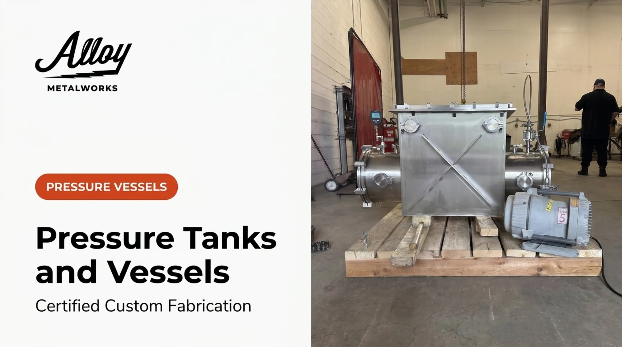
A pressure vessel is a closed container built to hold gas or liquid at pressure substantially different from atmospheric. ASME's Section VIII, Division 1 scope applies to vessels operating above 15 psig — a useful reference point, though it's an ASME scope boundary, not a universal legal threshold. Jurisdictional rules and exemptions still apply on top of it.
Why Vessels Split Lengthwise, Not End to End
For a thin-walled cylinder, hoop stress equals Pr/t (pressure times radius, divided by thickness). Longitudinal stress is half that. Since hoop stress is twice as high, a crack running parallel to the vessel's axis gets pulled open harder than one running around it. That's why cylindrical vessels typically fail by splitting lengthwise rather than blowing off an end cap.
Spherical vessels distribute stress evenly in both directions, which is why they're often chosen for large-volume, high-pressure storage despite being harder to fabricate.

Where These Vessels Show Up
- Aerospace and space technology — propellant tanks, pneumatic systems
- Hydrogen and clean energy — storage tanks, fuel cell components
- Chemical processing — reactors, separators
- Food and pharma — sanitary process vessels
- Research — experimental and cryogenic equipment
Material Selection Drivers
- Carbon steel — cost-effective for moderate pressure and non-corrosive service
- Stainless steel — corrosion resistance, sanitary applications
- Nickel alloys (Inconel, Hastelloy) — high-temperature and highly corrosive chemical environments
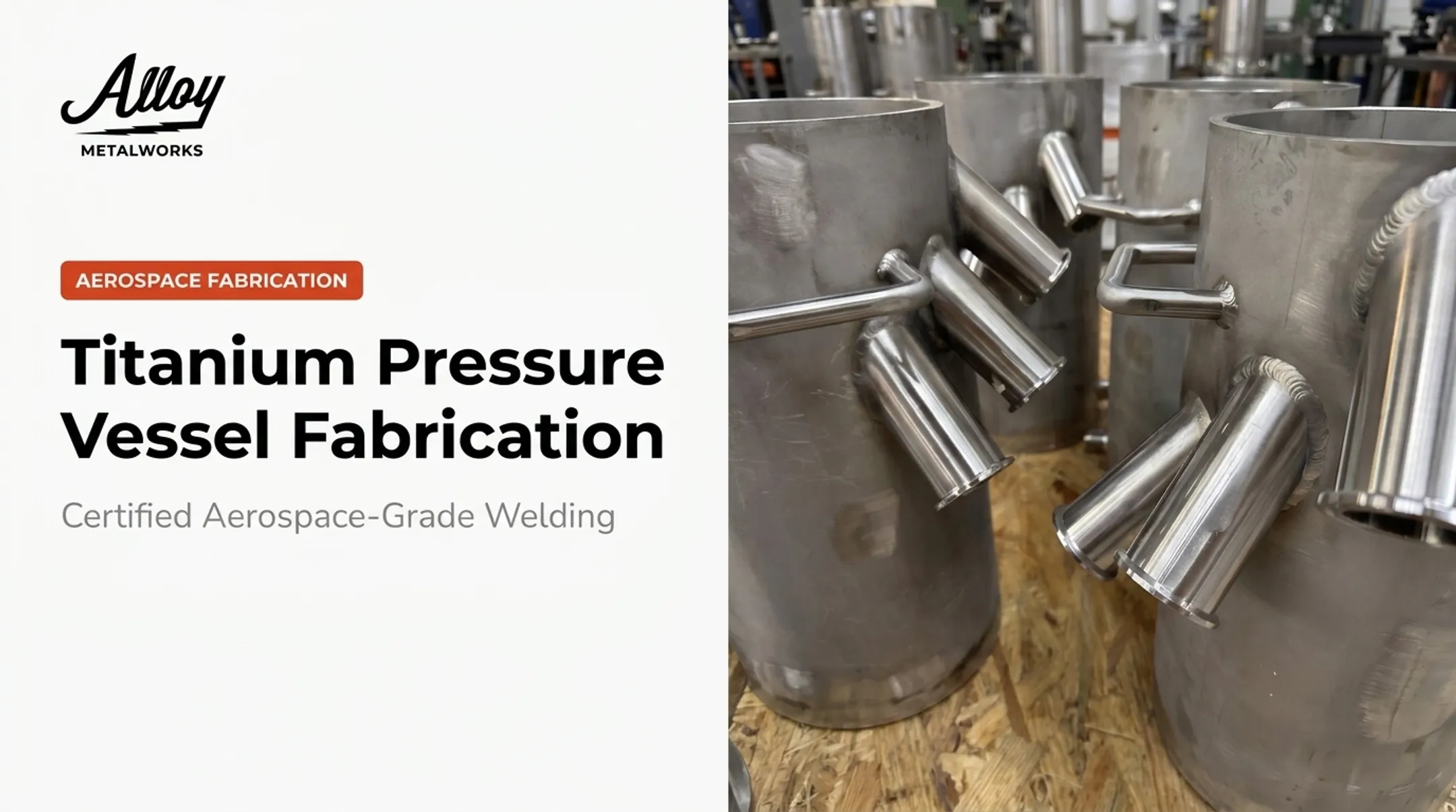
- Titanium — strength-to-weight ratio, corrosion resistance
- Aluminum — weight-sensitive, moderate-pressure applications
Alloy Metalworks regularly fabricates in the specialty alloys from this list, including Inconel 600, 601, 617, 625, and 718, Hastelloy, Incoloy 800HT, and multiple titanium grades. Energy and aerospace clients rarely stick to one alloy across a project.
Types of Pressure Vessels
Geometry-Based Classification
Most pressure vessels fall into one of two geometry families:
- Cylindrical shells with formed heads — torispherical, ellipsoidal, or hemispherical; the workhorse layout for process and industrial service
- Spherical vessels — harder to fabricate, but distribute stress more efficiently for large-volume, high-pressure storage
Composite Classifications: Type 1 Through Type 4
The Department of Energy defines four vessel types based on liner and reinforcement:
| Type | Construction | Load-Bearing Element |
|---|---|---|
| I | All-metal cylinder | Metal wall only |
| II | Metal liner, hoop-wrapped | Liner + hoop reinforcement |
| III | Metal liner, fully wrapped | Composite overwrap (axial + hoop) |
| IV | Polymer liner, fully wrapped | Composite overwrap only |
Type 4 vessels use a non-load-bearing polymer liner wrapped in axial and hoop composite fiber, so they dominate weight-sensitive service such as hydrogen fuel cell tanks, SCBA gear, and aerospace systems.

ASME Section VIII: Divisions 1, 2, and 3
- Division 1: Conventional, prescriptive rules for common shell and head geometries
- Division 2: Alternative rules with analytical Part 5 methods, often paired with FEA on complex designs
- Division 3: Alternative rules for high-pressure vessels, with a stated maximum design pressure of 15,000 psi
No fixed pressure cutoff cleanly separates these Divisions. Confirm the choice against the current Boiler and Pressure Vessel Code edition, the vessel geometry, the construction type, and actual service conditions.
The Engineering and Design Process
Before any calculation begins, engineers need to lock down the design basis: design pressure and temperature, corrosion allowance, material selection, load cases, and the governing code edition. Skip this step, and everything downstream is built on guesswork.
Thickness and Joint Efficiency
Wall thickness calculations depend on design pressure, material allowable stress, vessel radius, and joint efficiency (E), a code-defined factor tied to weld category and inspection level, not a material property. Full radiography versus spot examination can change required thickness enough to alter the design, so the exact code edition and examination level matter.
Loads Beyond Internal Pressure
A vessel that only accounts for internal pressure isn't finished. Engineers also need to check:
- Wind and seismic loading for vertical vessels
- Transportation loads during shipping
- Lifting loads during installation
- Nozzle and piping loads transmitted from connected systems
When FEA Enters the Picture
Finite Element Analysis becomes essential for complex geometries, local stress concentrations, and most ASME Section VIII Division 2 or 3 designs. FEA only holds up with defined boundary conditions, mesh convergence checks, and proper stress classification. A stress plot alone is not analysis.
A coherent design package (drawings, datasheet, and calculation report) matters as much as the math itself. Alloy Metalworks builds this collaboration into how it works: weld procedure development, distortion control, and joint design support happen alongside engineering, not after it. That reduces shop queries and rework because the fabricator understands design intent from day one, not just the drawing dimensions.
Materials, Welding, and Fabrication Standards
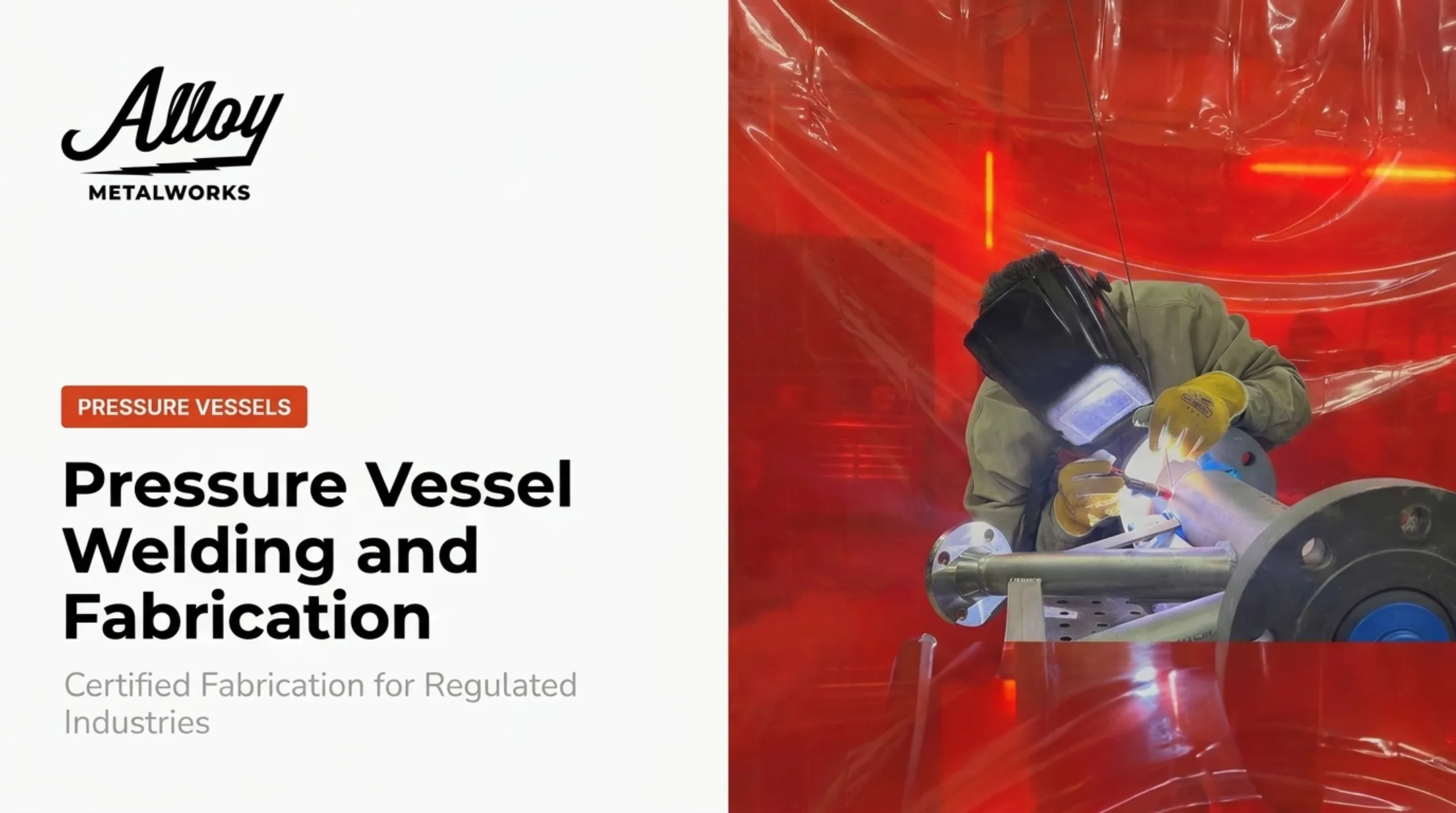
Welding is often the weakest link in an otherwise sound vessel design. Material choice sets the baseline: alloys must match design pressure, temperature, and corrosion service under the governing construction code. Code-qualified welding under ASME Section IX then governs procedure and welder qualification across GTAW, GMAW, SMAW, and SAW. Qualification alone does not guarantee a compliant vessel; it has to be applied correctly within that construction code.
Fabrication Steps
- Cutting and forming shell and head sections
- Welding shell seams, heads, and nozzle attachments
- Post-weld heat treatment (PWHT) where required
- Fitting and nozzle attachment with verified alignment
Specialty Alloy Challenges
Titanium oxidizes readily at elevated temperature, so welding it requires controlled purge setups: argon-filled chambers with tight oxygen and moisture control. Alloy Metalworks uses custom inert gas chambers for this reason; titanium purge quality directly affects whether a weld holds up in service.

Nickel-based alloys like Inconel and Hastelloy bring their own risks: hot cracking, grain-boundary precipitation, and porosity if heat input and cleanliness aren't tightly controlled.
When Alloy Metalworks fabricated an Alloy 800HT thermochemical reactor component rated for operation above 700°C for the National Renewable Energy Laboratory, that work led to the company being added to NREL's pressure program as an approved vendor.
Alloy Metalworks holds ASME Section IX, AWS D17.1, and ISO 9001 certifications, with the documentation and traceability engineers need for audit-ready vessel work.
Testing, Inspection, and Documentation
NDE Methods
| Method | Detects | Common Use |
|---|---|---|
| Radiographic (RT) | Internal structure via imaging | Volumetric weld examination |
| Ultrasonic (UT) | Surface and subsurface flaws | Thickness and weld checks |
| Magnetic particle (MT) | Surface/near-surface flaws | Fast screening on ferromagnetic metals |
| Liquid penetrant (PT) | Surface flaws | Nonporous material surfaces |

Hydrostatic Testing
Before a vessel enters service, it undergoes a hydrostatic pressure test, typically well above maximum allowable working pressure per the governing BPVC provision for the specific Division and edition in use. That test is the final proof the vessel holds design pressure in the shop, not only on paper.
Documentation That Actually Matters
Inspection-ready records prevent downstream delays and support audits: material test reports (MTRs), weld procedure specifications, welder qualifications, and NDE reports.
Alloy Metalworks has seen the alternative firsthand. On a piping rebuild inspected to ASME B31.3, work from a previous contractor failed inspection because no documentation existed for the welds, procedures, or welder qualifications. The replacement scope included in-house borescope and dye-penetrant testing before third-party inspection started.
Common Design and Fabrication Mistakes to Avoid
Even technically sound designs run into trouble during fabrication. The most frequent issues:
- Underestimating secondary loads — wind, seismic, or transportation loads treated as an afterthought
- Poor weld joint design — geometry that looks fine on paper but is difficult to weld consistently
- Inadequate material selection — choosing a metal based on cost rather than service compatibility
- Missing relief devices — a design gap that turns a controllable overpressure into a failure
- Weak documentation — no traceability when something needs verifying later
Isolated component checks don't guarantee a good vessel. A shell that passes calculations, a nozzle that passes calculations, and a flange that passes calculations don't automatically add up to a vessel that performs safely as a whole system.
Working with a fabrication partner who understands engineering intent, not just drawing dimensions, catches these issues before they become expensive rework. Early design-to-build collaboration flags problems before work starts, instead of discovering a joint design flaw halfway through a weld pass.
Frequently Asked Questions
What is a pressure vessel?
A pressure vessel is a sealed container engineered to safely hold gas or liquid at a pressure significantly different from atmospheric pressure. ASME Section VIII governs design and construction for vessels above 15 psig.
What are the types of pressure vessels?
Vessels are classified by geometry (cylindrical with formed heads, or spherical) and, for composite construction, by DOE Types 1 through 4 based on liner material and reinforcement approach.
What is a Type 4 pressure vessel?
A Type 4 vessel uses a non-load-bearing polymer liner fully wrapped in composite fiber. It's valued for its light weight in hydrogen storage and aerospace applications where every pound counts.
How is a pressure vessel's wall thickness determined?
Thickness depends on design pressure, material allowable stress, vessel radius, and joint efficiency — a code-defined factor tied to the weld category and inspection level used.
Why does welding quality matter so much in pressure vessel safety?
Welds are typically the weakest point in a vessel, so they require code-qualified procedures under ASME Section IX and verification through non-destructive examination before the vessel enters service.
What codes govern pressure vessel design in the US?
ASME's Boiler and Pressure Vessel Code, Section VIII, Divisions 1 through 3, is the primary US standard, from conventional prescriptive design through high-pressure alternative rules.